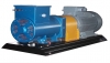
Ürünlerimizden bazıları

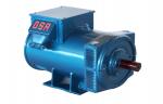
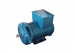
Sürekli Güç : 150 kVA
Standby Güç : 165 kVA
Devir : 1500 d/d
Frekans : 50 Hz
Gerilim : 231/400 Volt
Tip : GSA 421S/4
Tahrik Gücü : 181 HP
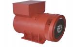
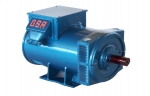
Sürekli Güç : 500 kVA
Standby Güç : 550 kVA
Devir : 1500 d/d
Frekans : 50 Hz
Gerilim : 231/400 Volt
Tip : GSA 538L/4
Tahrik Gücü : 587 HP
Standby Güç : 550 kVA
Devir : 1500 d/d
Frekans : 50 Hz
Gerilim : 231/400 Volt
Tip : GSA 538L/4
Tahrik Gücü : 587 HP
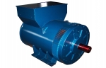
Sürekli Güç : 1500 kVA
Standby Güç : 1650 kVA
Devir : 1500 d/d
Frekans : 50 Hz
Gerilim : 231/400 Volt
Tip : GSA 689L/T4
Tahrik Gücü : 1689 HP
Standby Güç : 1650 kVA
Devir : 1500 d/d
Frekans : 50 Hz
Gerilim : 231/400 Volt
Tip : GSA 689L/T4
Tahrik Gücü : 1689 HP
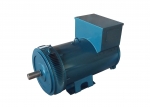
Sürekli Güç : 100 kVA
Standby Güç : 110 kVA
Devir : 1500 d/d
Frekans : 50 Hz
Gerilim : 231/400 Volt
Tip : GSA 341L/4
Tahrik Gücü : 122 HP

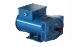
Sürekli Güç : 200 kVA
Standby Güç : 220 kVA
Devir : 1500 d/d
Frekans : 50 Hz
Gerilim : 231/400 Volt
Tip : GSA 422M/4
Tahrik Gücü : 238 HP
Standby Güç : 220 kVA
Devir : 1500 d/d
Frekans : 50 Hz
Gerilim : 231/400 Volt
Tip : GSA 422M/4
Tahrik Gücü : 238 HP
Sürekli Güç : 30 kVA
Standby Güç : 33 kVA
Devir : 3000 d/d
Frekans : 50 Hz
Gerilim : 231/400 Volt
Tip: GSA 276LL/2
Tahrik Gücü : 39 HP
Standby Güç : 33 kVA
Devir : 3000 d/d
Frekans : 50 Hz
Gerilim : 231/400 Volt
Tip: GSA 276LL/2
Tahrik Gücü : 39 HP
Sürekli Güç : 40 kVA
Standby Güç : 44 kVA
Devir : 1500 d/d
Frekans : 50 Hz
Gerilim : 231/400 Volt
Tip : GSA 272L/4
Tahrik Gücü : 50 HP
Sürekli Güç : 350 kVA
Standby Güç : 385 kVA
Devir : 1500 d/d
Frekans : 50 Hz
Gerilim : 231/400 Volt
Tip : GSA 535M/4
Tahrik Gücü : 412 HP
Standby Güç : 385 kVA
Devir : 1500 d/d
Frekans : 50 Hz
Gerilim : 231/400 Volt
Tip : GSA 535M/4
Tahrik Gücü : 412 HP
Sürekli Güç : 1230 kVA
Standby Güç : 1353 kVA
Devir : 1500 d/d
Frekans : 50 Hz
Gerilim : 231/400 Volt
Tip : GSA 687L/4
Tahrik Gücü : 1392 HP
Standby Güç : 1353 kVA
Devir : 1500 d/d
Frekans : 50 Hz
Gerilim : 231/400 Volt
Tip : GSA 687L/4
Tahrik Gücü : 1392 HP
Sıkça Sorulan Sorular
Alternatörde sürekli ve standby güç nedir?
H sınıfı ve F sınıfı ne demektir?
Alternatörde güç ihtiyacı nasıl belirlenir?
Su türbini imal ediyor musunuz? Alternatör alsam kendim su türbini yapabilir miyim?
Alternatör etiketindeki ortam sıcaklığı ne anlama gelir?
Jeneratörler dizel motorlarında niçin ağır tip volan kullanılır?
Alternatör yapısı nasıldır?
Fırçasız alternetörlerin çalışma prensibi nasıldır?
Alternatör düşük veya yüksek devirde çalıştırılırsa ne olur?
Sabit mıknatıslı alternatörler nerede kullanılır?
Küçük bir elektrik motoru ile daha güçlü bir alternatör çevirebilir miyim?
TRAKTÖR JENERATÖRÜ
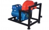 TRAKTÖR kuyruk milinden hareket alan jeneratörler.
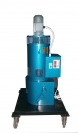
Frekans Konvertörü
 Frekans Konvertörleri
Frekans: 100--400 Hz
Devir: 750-3000d/d
Kullanım Alanları:
- Trafo testleri
- Uçak Yer Destek Üniteleri
- Yüksek frekans gerektiren özel uygulamalar
Endüktif Yük - Döner Trafo
 Endüktif Yük: Jeneratör yüklemelerinde istenilen güç faktöründe yüklemek için kullanılır.
Döner Trafo: Voltajı kademesiz olarak ayarlamada kullanılan kademesiz trafolardır.